T-Handle
Intermediate-axis instability in torque-free rigid-body rotation
The intermediate axis theorem — also called the tennis racket theorem or Dzhanibekov effect — states that free rotation of a rigid body about the axis with the middle-valued principal moment of inertia is unstable. Even the smallest perturbation causes the body to periodically flip 180° and reverse its apparent spin direction, while both angular momentum and kinetic energy remain exactly conserved throughout.
A T-handle creates three clearly unequal moments: the long cross-bar gives a small Ixx (spinning like a baton about its own long axis), the asymmetric T-shape gives an intermediate Iyy about the stem axis, and the combined off-axis mass distribution gives the largest Izz out of the plane of the T. The ordering Ixx < Iyy < Izz makes the body Y-axis — pointing up through the stem — the unstable intermediate axis.
The Space Station Connection
The effect was first captured on film in 1985 by Soviet cosmonaut Vladimir Dzhanibekov aboard the Mir space station, who observed a wing nut spontaneously reverse direction after being spun off a bolt in weightlessness. The footage became a widely shared demonstration of the phenomenon, and it now bears his name. NASA astronauts aboard the International Space Station have since repeated the experiment deliberately with T-handles, as shown in the video below — real hardware flipping in exactly the manner simulated here.
Physics
A torque-free rigid body conserves two scalar quantities: total angular momentum magnitude and rotational kinetic energy. Together these constraints force the body’s angular velocity vector — expressed in the body frame — to trace a fixed closed curve called the polhode: the intersection of a constant-energy ellipsoid with a constant-angular-momentum sphere. For a body with three distinct principal moments, the polhode near the intermediate axis is a separatrix that connects regions of positive and negative intermediate-axis spin. As the angular velocity vector cycles along this separatrix it alternates between the two poles at ±ωy, which from the outside appears as a periodic 180° flip of the body. The minimum and maximum inertia axes are stable — small perturbations produce closed polhodes that return near the starting point — while the intermediate axis is a saddle.
MJCF Model
Setting gravity="0 0 0" places the body in simulated free space, removing any gravitational torque and isolating the conservative rotational dynamics:
<option gravity="0 0 0" integrator="RK4" timestep="0.001"/>
The T-shape is built from two box geoms sharing a single parent body; MuJoCo computes the composite center of mass and inertia tensor automatically from the geometry and density:
<geom name="bar"    type="box" size="0.1  0.01 0.01"                 material="steel" density="7700"/>
<geom name="handle" type="box" size="0.01 0.05 0.01" pos="0 0.06 0"  material="steel" density="7700"/>
The 200 mm cross-bar extends along the body X-axis; the 100 mm handle piece is offset 60 mm in Y so its bottom face sits flush with the top of the bar, forming the stem of the T. This geometry shifts the combined center of mass 20 mm up the stem and produces the Ixx < Iyy < Izz ordering needed for the intermediate-axis instability.
Initial Conditions
Spinning exactly about the intermediate axis with no perturbation is an unstable equilibrium — the body would maintain constant ωy indefinitely without ever flipping.
The seed value SEED_PERTURB = 0.05 rad/s about the X-axis represents the inevitable imperfection when manually spinning any real object, and is enough to excite the instability and trigger the first flip within a few seconds.
Video
The video shows the T-handle drifting freely in zero gravity, with the stem periodically reversing direction — pointing one way, then 180° the other, then back again, roughly once every four seconds. The transition is not a sudden snap: the body rocks through a brief high-energy tumble at each reversal, during which all three rotation axes are simultaneously active, before settling into the opposite spin direction.
Plots
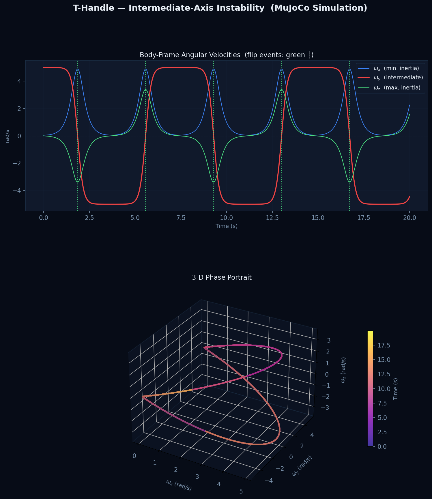
The top panel shows all three body-frame angular velocity components over time. The red ωy trace (intermediate axis) follows a square-wave pattern, spending most of each period near ±5 rad/s with smooth transitions between — each zero-crossing corresponds to one flip event, marked by a green dotted vertical line. During each transition ωx (blue) and ωz (green) spike briefly as angular velocity disperses across all three axes; outside these windows they remain close to zero.
The bottom 3-D phase portrait shows the angular velocity vector tracing two lobes in body-fixed coordinates, coloured by time from purple (early) to yellow (late). The left lobe corresponds to positive ωy spin and the right to negative; the narrow passages at ωy ≈ 0 are the instants of maximum tumble during each flip, where ωx and ωz reach their peak values. The trajectory revisits the same two-lobed curve on every cycle, confirming that the motion is periodic and the conserved quantities remain constant throughout.
Running the Simulation
cd t_handle
python t_handle_sim.py
| File | Contents |
|---|---|
t_handle_sim.mp4 |
Rendered 3-D video (1280 × 720, 60 fps) |
t_handle_states.png |
Angular velocity time history and 3-D phase portrait |
See Setup & Installation for environment and dependency instructions.
Live Simulation
Downloading MuJoCo WASM (~10 MB)…