Four-Bar Linkage
Closed-loop planar mechanism with an equality constraint
A four-bar linkage is the simplest closed-loop planar mechanism: three moving rigid links — crank, coupler, and follower — each connected by frictionless pin joints, with the two outer pivots fixed to a stationary ground link. Given one generalized coordinate (the crank angle), the configuration of the entire mechanism is determined by the kinematic closure constraint.
Kinematics
Placing the crank pivot at the origin and the follower pivot at $(l_3, 0)$, the loop-closure equation requires that the chain of links forms a closed polygon:
\(l_0 \cos\theta_0 + l_1 \cos\theta_1 + l_2 \cos\theta_2 = l_3\) \(l_0 \sin\theta_0 + l_1 \sin\theta_1 + l_2 \sin\theta_2 = 0\)
where $\theta_0$, $\theta_1$, $\theta_2$ are the world-frame angles of the crank, coupler, and follower, respectively, measured from the positive $x$-axis.
Grashof Condition
For a four-bar linkage to have at least one link capable of continuous rotation, the sum of the shortest and longest link lengths must not exceed the sum of the remaining two:
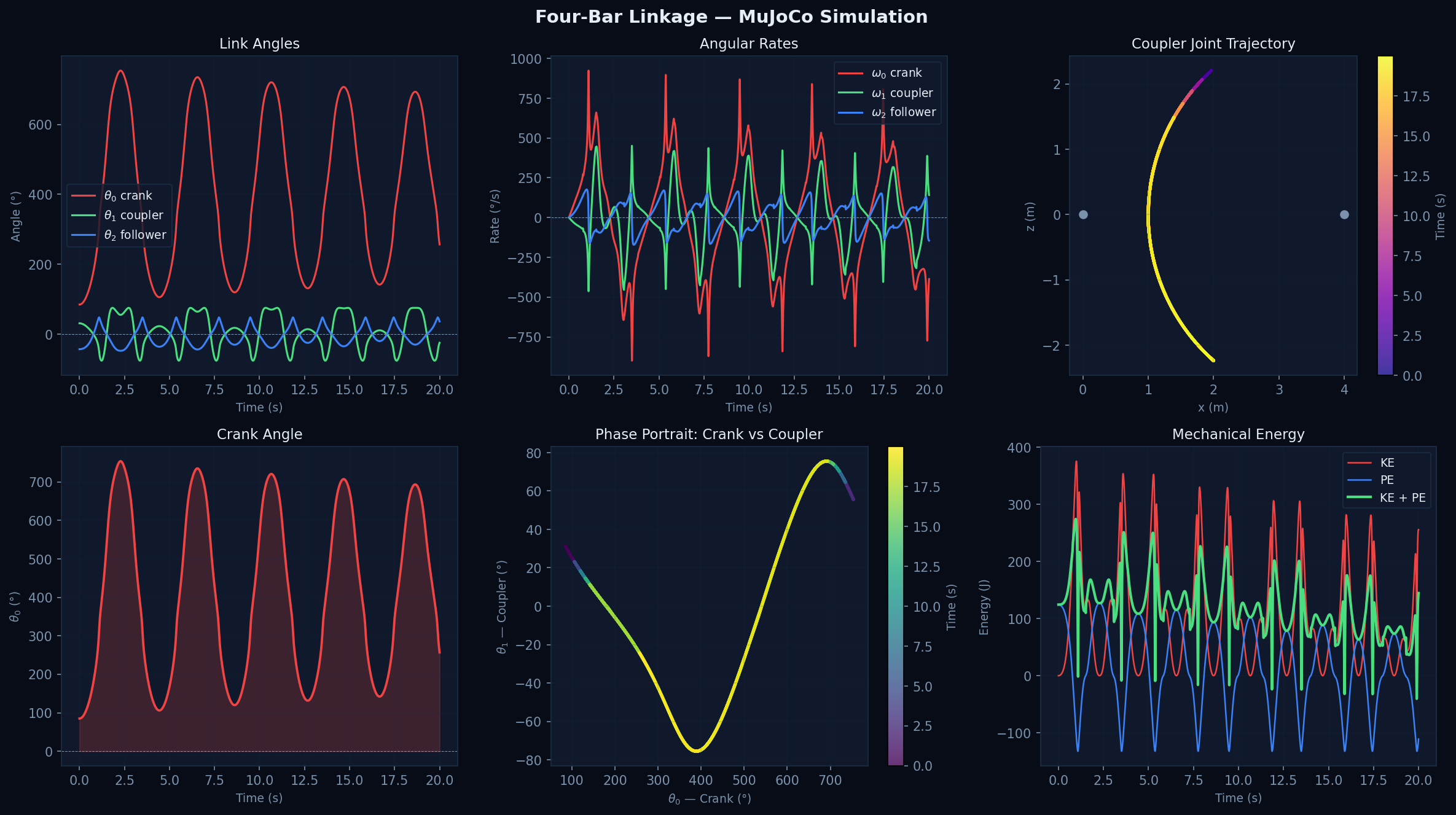
\[l_\text{min} + l_\text{max} \leq l_1 + l_2 \quad \Rightarrow \quad 1 + 4 = 2 + 3 = 5\]This linkage sits exactly on the Grashof boundary (equality), making it a change-point mechanism. With the ground link as the longest and the crank as the shortest, it would theoretically permit full crank rotation, but the mechanism passes through collinear (folded) configurations at the change points. Starting at $\theta_0 = 85°$ with all velocities zero, the system oscillates rather than completing full rotations — gravity alone drives the motion.
MJCF Model
Joint Conventions
MuJoCo joints are always relative to the parent body frame, so the coupler joint angle $q_1$ is measured from the crank body frame, not the world frame. The conversion between notebook (world-frame) angles $\theta_k$ and MuJoCo joint angles $q_k$ is:
\[q_0 = \theta_0, \qquad q_1 = \theta_1 - \theta_0, \qquad q_2 = -\theta_2\]The crank and coupler joints rotate about the $-y$ axis so that positive angles sweep upward (+z) in world frame. The follower joint uses $+y$ because its body extends in the $-x$ direction from its pivot:
<joint name="j0" type="hinge" axis="0 -1 0"/>  <!-- crank -->
<joint name="j1" type="hinge" axis="0 -1 0"/>  <!-- coupler (child of crank) -->
<joint name="j2" type="hinge" axis="0  1 0"/>  <!-- follower (extends in −x) -->
Closure Constraint
The loop-closure equation is enforced by a MuJoCo <connect> equality constraint, which drives the coupler tip and follower tip to coincide:
<site name="coupler_tip"  pos="2 0 0"/>   <!-- in coupler body: 2 m along +x from pivot P₁ -->
<site name="follower_tip" pos="-3 0 0"/>  <!-- in follower body: 3 m along −x from pivot P₃ -->

<equality>
  <connect site1="coupler_tip" site2="follower_tip"/>
</equality>
Named sites define the attachment points in each body’s local frame; <connect> then constrains those two world-frame positions to be equal at all times.
MuJoCo’s constraint solver enforces this pin joint via a velocity-level correction plus a Baumgarte stabilization force, keeping the linkage closed without any explicit position-level correction loop in user code.
Inertia
Each link is modeled as a uniform thin rod; the moment of inertia about the center of gravity for rotation out of plane is:
\[I_k = \frac{m_k l_k^2}{12}\]giving $I_0 = 0.0833$, $I_1 = 0.6667$, $I_2 = 2.25\ \text{kg·m}^2$.
Simulation
Energy Computation
Because MuJoCo joint angles are relative, recovering world-frame quantities requires the inverse conversion $\theta_0 = q_0$, $\theta_1 = q_0 + q_1$, $\theta_2 = -q_2$ applied at every step. The script then computes kinetic and potential energy analytically using thin-rod kinematics, providing an independent energy-conservation check that is separate from MuJoCo’s internal integrator.
Plots
Six panels track the evolution of the mechanism over 20 seconds. The link angles panel shows the world-frame angles $\theta_0$, $\theta_1$, $\theta_2$ oscillating as the linkage swings under gravity. The angular rates panel shows the corresponding world-frame rates. The coupler-joint trajectory (top right) traces the path of the coupler-follower pin P₂ in the $xz$-plane, colored by simulation time. The crank angle panel (bottom left) highlights the oscillatory character of $\theta_0$. The phase portrait (bottom center) plots $\theta_0$ vs $\theta_1$ with time-colored points, revealing the constrained relationship between the two angles imposed by the closure equation. The energy panel (bottom right) overlays KE, PE, and their sum; a flat total-energy line confirms that MuJoCo’s RK4 integrator preserves mechanical energy to within numerical tolerance over the full run.
Running the Simulation
cd four_bar_linkage
python four_bar_linkage_sim.py
Outputs written to the same directory:
| File | Contents |
|---|---|
four_bar_linkage_sim.mp4 |
Rendered 3-D video (1280 × 720, 60 fps) |
four_bar_linkage_states.png |
Six-panel state plots |
See Setup & Installation for environment and dependency instructions.
Live Simulation
Downloading MuJoCo WASM (~10 MB)…